Flared Wingwalls, Full Height Headwalls and Cutoff Walls
It is always desirable for a new structure to have flared wingwalls, matched into the channel banks at the inlet and outlet, to smoothly transition flow and protect the structure and roadway approaches from erosion. It is also recommended that full height concrete headwalls be constructed at the inlet and outlet. Any closed bottom structure should also be equipped with cutoff walls, extending to a depth equal to the culvert rise, up to 4 feet, or to ledge, to serve as undermining prevention. Any new structure should be properly aligned with the channel, span the natural channel width, and be constructed on a grade that matches the channel.
More information: Hydraulics Manual, Section 6.4.3.5: End Treatment (Inlet of Outlet)

Figure 24: Flared wingwalls route stream flow into the structure and retain material from the roadway embankment. They are particularly important when the culvert is skewed to the channel flow. Headwalls retain material over a buried structure. Cutoff walls, extending vertically beneath the streambed, are important for undermining prevention. Undermining, also called piping or undercutting, occurs when water runs beneath the structure, resulting in sediment transport. Over time, a large amount of sediment transport can result in sinkholes and may ultimately compromise the structural integrity of the structure.
Bed Retention Sills
Bed retention sills are retrofits for structures that are embedded and infilled with E-stone. Unless otherwise specified, sills should be 12 inches high at the edges of the box and 6 inches high in the center, creating a V-shape across the full width of the box. Sills should be spaced no more than 8 feet apart throughout the structure with one sill placed at both the inlet and the outlet. The structure should then be filled level to the streambed with the specified E-stone, allowing flow to be kept above the surface, providing the conditions necessary for aquatic organism passage.

Figure 25: Interior of a four-sided concrete box culvert with bed retention sills exposed before evenly distributing infill material (E-stone). Bed retention sills improve the likelihood that the structure to retain the E-stone. Infill material is essential for aquatic organism passage, and increases the interior roughness of the crossing, reducing velocities and extent of erosion.
Shallow Bedrock Profile
If ledge is encountered, a buried structure may be difficult to install, and an open bottom structure may be desirable for constructability.
More information: Hydraulics Manual, Section 6.3.1: Structure Type Selection
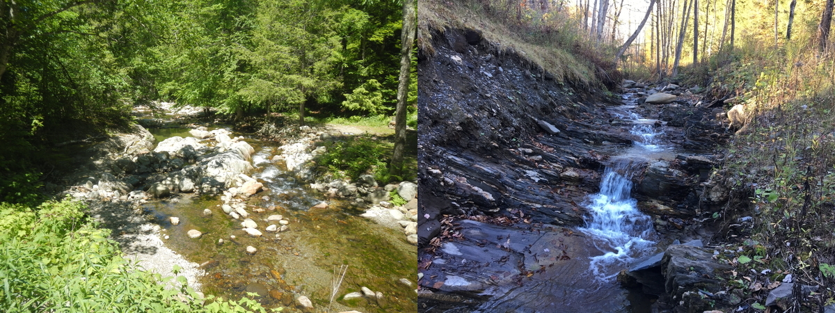
Figure 26: Brush Brook along Camel’s Hump Road in Huntington, VT (left); unnamed stream along Flint Road in Williamstown, VT (right). A shallow bedrock profile within the vicinity of the structure indicates that ledge may be encountered during excavation. Solid rock removal is known to be a costly and time-consuming process. It may be desirable to consider structures founded on footings, such as an open bottom arch. With this structure type, a subfooting may be poured directly on ledge, creating a flat surface with which scour resistant substructure may be founded.
Open Bottom Structures
For open bottom structures, the specified E-stone should be used to build the channel through the structure. The bottom of abutment footings should be at least 6 feet below the channel bottom, or to ledge, to prevent undermining. Abutments on piles should be designed to be free standing for a scour depth at least 6 feet below channel bottom.
More information: Hydraulics Manual, Chapter 7: Channel Stability and Scour at Bridges
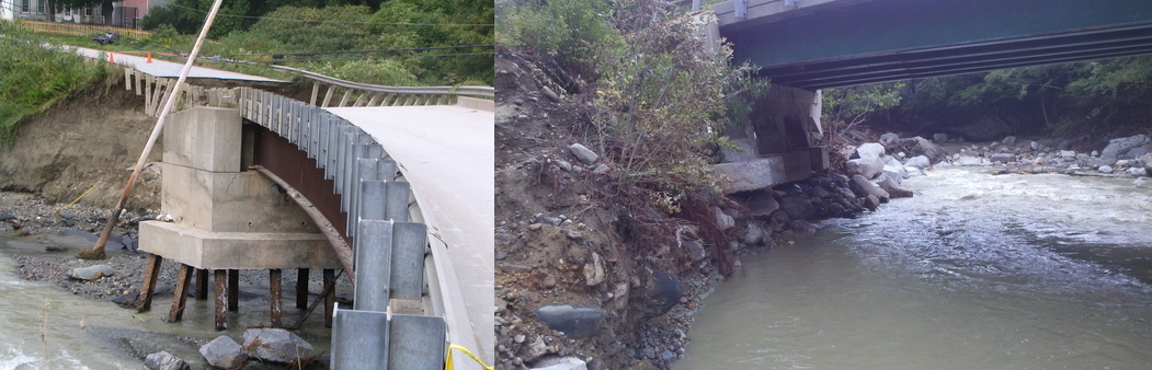
Figure 27: Impacts of scour on a bridge abutment (left). This pier was designed for a free-standing scour depth of over 6 feet below channel bottom, allowing this pier to maintain structural integrity though the floodwaters of T.S. Irene. Exposed footings at a bridge abutment (right). This is an example of substructure that is not scour resilient. High flows on this structure could wash away the material that the structure is founded on, compromising the structural integrity of the bridge.
Cover Limitations
The low height from the streambed to the road can limit replacement options to a box structure, as the roadway may have to be substantially raised for a pipe. An increase in roadway elevation could create a dam, thereby increasing the extent of flooding upstream. Pipe manufacturers can provide specific recommendations regarding minimum and maximum fill heights and required pipe thickness.

Figure 28: Pipe arch with minimal cover in Middlesex, VT. Recommendations for this structure were limited to a concrete box as the road would need to be raised to meet the manufacturer’s minimum requirements for cover over a pipe. Elevating the roadway is known to create a dam, thereby increasing extent of flooding upstream. Due to the presence of a FEMA Flood Insurance Study, and the proximity of adjacent residential property, base flood (1% AEP) elevations for this area are regulated and must not be adversely impacted existing configuration.
Debris and Constructability
Recommended structures are sized with respect to hydraulic and environmental standards and do not account for debris blockage complications. Structures are often recommended based on minimum clear height necessary for hydraulic adequacy. To minimize maintenance and ensure constructability, it is recommended that the structure height be adequate for installation of E-stone and passage of debris.
More information: Hydraulics Manual
- Section 6.3.5: Debris Control
- Section 7.4.5: Debris and Ice
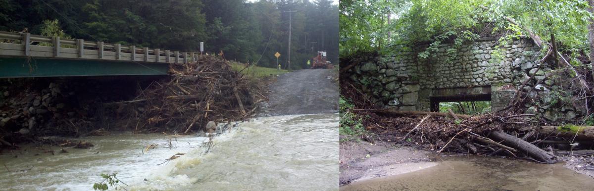
Figure 29: Debris caught at a structure opening can result in a large reduction in hydraulic capacity. Further escalation without removal of debris may result in the structure plugging, which is known to increase floodwaters upstream and has the potential to contribute to structural failure. Although we recommend that the structure be constructed at a span equal to bankfull width for perennial streams, provided clear heights are often minimums. Consideration of local debris passage is especially when there is active beaver habitat upstream. Furthermore, for constructability it is important that the structure provide a clear height that allows for the installation of infill material (E-stone) during construction.
Stone Fill Slope Protection
At the size specified in the hydraulics memo, stone fill should be used to protect any disturbed channel banks or roadway slopes at the inlet and outlet, up to a height of at least one-foot above the top of the opening. It may be necessary to place stone around the outlet of the structure to reduce scour and erosion. Stone should not constrict the channel or structure opening.
More Information: Hydraulics Manual
- Section 5.3.2: Stream Channels
- Section 6.4.4.2: Outlet Protection
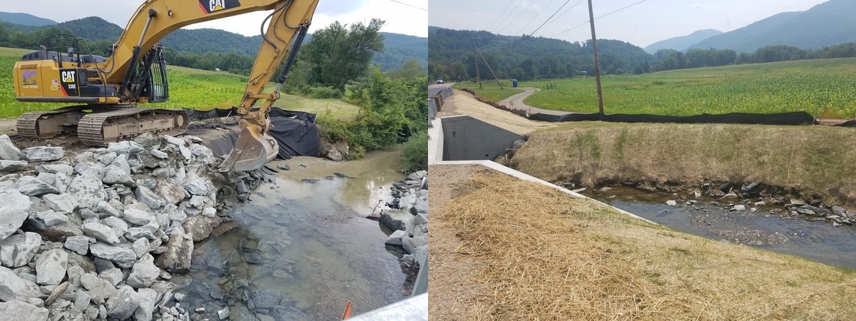
Figure 30: Outlet of Richmond US-2 Bridge 32 over Snipe Island Brook. Disturbed channel banks being reconstructed with stone fill (left) and covered with grubbing material and erosion control matting (right). These additional features work to reduce erosion and assist in restoring a semblance of the natural condition of the channel.

Figure 31: Bradford VT-25B Bridge 1 over Waits River. Stone fill beneath the abutments works to mitigate scour and erosion. Additional stone fill along channel banks dissipates energy that would otherwise erode material surrounding the structure and adjacent channel banks during large magnitude events. Stone size is selected based on anticipated main channel velocities during the design event.
Historic Structures
Stone culverts have served as important elements in Vermont’s developing road network and typically possess characteristics that associate them with early highway design and construction. These characteristics may be significant and qualify the culverts to be considered historic. A stone culvert may be considered historic if it is over fifty years of age and in fair to good condition. Whenever possible, it is desirable to retain such historic features in the Vermont landscape if doing so is technically and economically feasible. Before deciding to replace a stone culvert, please consider if there is another location nearby that could accommodate a new culvert, meet hydraulic standards, and be appropriate for your town, thus allowing the town to retain the stone culvert. If, after consideration of other locations, the town determines that replacing the stone culvert is the only feasible alternative, please be aware that use of state or federal funds for the replacement project will require an environmental review and may require mitigation to compensate for the loss of the historic resource, such as hiring a qualified architectural historian to photograph and document the stone culvert prior to removal.
More information: Vermont Statewide Historic Stone Culvert Inventory, Stone Highway Culverts in Vermont 1750 to 1930. This document, prepared for VTrans by the Historic Documentation Company of Portsmouth RI, will be published soon.
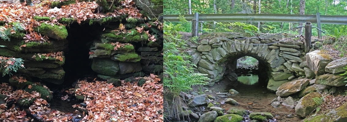
Figure 32: Historic stone culvert along an abandoned corridor in Calais, VT (left); Segmental stone arch spanning 80 inches, located on Hill Road, Brookline (right). This arch is built entirely of fieldstone, which includes a few naturally wedge-shaped stones, flat stones and shims to establish good contact between the primary arch stones. The upstream end of the culvert was lengthened about 12 feet with the addition of a concrete arch, visible in silhouette through the opening.
ANR River Management
Prior to any action toward the implementation of any recommendations received from VTrans, stream type and structure size must be confirmed, and may be modified, by the VT ANR River Management Engineer to ensure compliance with state environmental standards for stream crossing structures.
More information: Hydraulics Manual, Section 6.1.4.3: Other Agencies

Figure 33: ANR River Management Engineer districts and contact information. Each of the five districts in Vermont are assigned an ANR River Management Engineer (RME). The regional RME ensures that structures meet state stream equilibrium standards, as well as working with Fish and Wildlife to determine requirements for wildlife connectivity and aquatic organism passage. They also serve as a point of contact and oversight to ensure compliance with stream alteration rules, general permits and best management practices. Visit this domain to download this image.
Regulatory Authorities
Regulatory authorities including the US Army Corps of Engineers may have additional concerns or requirements regarding this structure.
More information: Hydraulics Manual, Section 6.2: Guidelines
Backwater
Structures directly upstream of a stream mouth and/or a large waterbody be affected by water backing up during flood flows on that waterbody. Further consideration is be required to determine the extent of this possibility as this analysis strictly addresses replacement options considering runoff volumes and environmental standards. Headwater depths may therefore be greater than reported if water backs up from a downstream waterbody.

Figure 34: Flooding along Lake Champlain after T.S. Irene. Floodwaters significantly increased water surface elevations along this waterbody, which also extends upstream from the mouth of a river. Water backing up a river can increase water surface elevations observed at upstream structures.
A More Detailed Study
Bridges of large spans (generally greater than 16-20 feet), a history of damage, or in a high-risk location warrant a more detailed hydraulic study if survey becomes available. The presence of nearby buildings and/or a Federal Emergency Management Agency Flood Insurance Study, further justifies the need for a more detailed study.
More information: Hydraulics Manual
- Section 1.3.4.3 Floodplains / Flood Hazard Areas
- Section 6.1.5.1 Federal Emergency Management Agency

Figure 35: Federal Emergency Management Agency Flood Insurance Study information is mapped and available at this online FIS portal. If there is a flood insurance study for the river of interest, any alternative is subject to FEMA floodplain and floodway regulations for backwater. Base flood (1% AEP) water surface elevations for any proposed alternative must not exceed those of the existing configuration.
Town and District Hydraulic Studies
The Hydraulics Unit is a dynamic group of professionals with the primary function of supporting the design and permitting of bridges and culverts compatible with Vermont’s rivers and streams. Town and district hydraulic studies are paid for in part by federal funding that also supports the operation and maintenance of a network of crest and continuous monitoring gauges statewide. It is our objective to use this funding to support the safe and efficient movement of people and goods as well as providing timely, accurate and cost-effective recommendations for flood damage areas or in support of hazard mitigation efforts.
Please note that recommendations are made without the benefit of a survey and are based on limited information. The final decision regarding replacement of this structure must comply with state regulatory standards, and should take into consideration matching natural channel conditions, roadway grade, environmental concerns, safety, and other requirements.
Previous page: Hydraulics Typical Drawings
Back to beginning: AOT Hydraulics