Embedded Box Culvert
Four-sided concrete boxes are often pre-fabricated and are commonly recommended for crossing structures on perennial streams. They offer significant advantage in areas that have low fill over the structure. The following encompasses typical details specified for this type of structure:
More Information: Hydraulics Manual, Figure 6-3: Typical Culvert Section Showing Embedded Materials

Figure 11: A perennial stream box culvert typical section. Tapered sills should be constructed to retain infill material (E-stone). Unless otherwise specified, sills should be 12 inches high at the edges of the box and 6 inches high in the center, creating a V-shape across the full width of the box. The structure should then be filled level to the streambed with the specified E-stone. Infill material allows flow to be kept above the surface, providing the conditions necessary for aquatic organism passage.
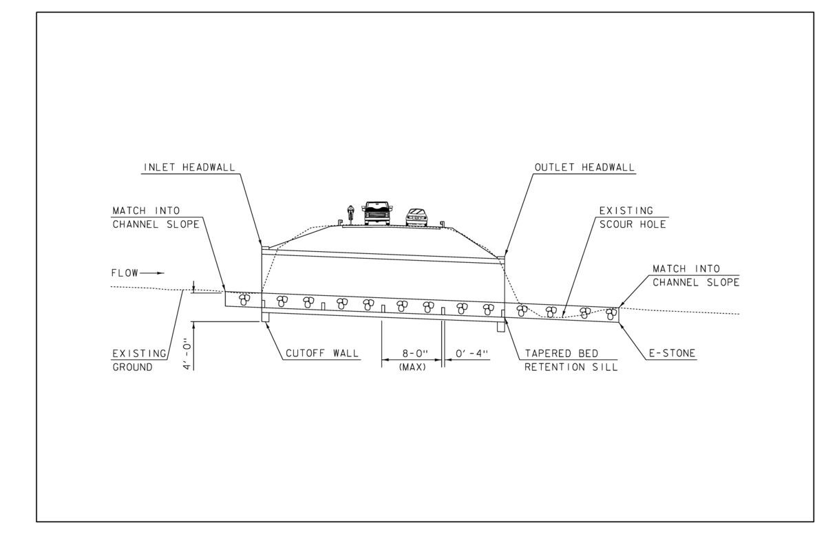
Figure 12: A perennial stream box culvert typical profile. Structures should be constructed on a grade that matches the existing stream slope and be equipped with full height headwalls at the inlet and outlet. A closed bottom structure should also be equipped with cutoff walls, extending to a depth equal to the culvert rise, up to 4 feet, or to ledge, to serve as undermining prevention. The structure should also be equipped with bed retention sills, which work to prevent infill material (E-stone) from washing out during large scale events. Sills should be spaced no more than 8 feet apart throughout the structure, with one sill at both the inlet and the outlet.
Open Bottom Arch or Rigid Frame
Open bottom arches, commonly constructed of steel or concrete, offer an advantage in ledge terrain. A shallow bedrock profile may require solid rock removal to make space for an embedded structure, a costly and time-consuming process. Open bottom arches however, can be founded on spread footings. When routed to ledge, footings provide a scour resistant substructure. The following details are typical for this structure type:
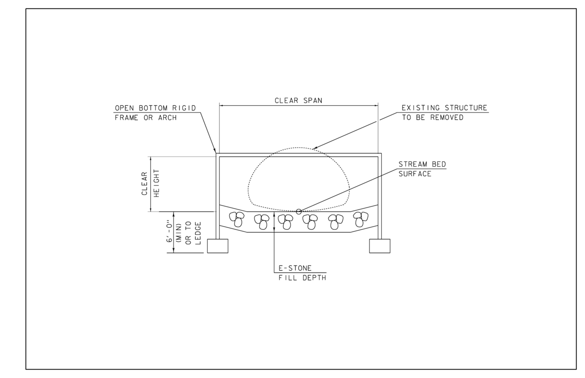
Figure 13: Open bottom arch or rigid frame typical section. The channel through the structure should be reconstructed with E-stone, at the specified stone fill depth. The bottom of abutment footings should be at least 6 feet below the channel bottom, or to ledge, to prevent undermining and protect against scour. Similarly, abutments on piles should be designed to be free standing for a scour depth at least 6 feet below channel bottom.
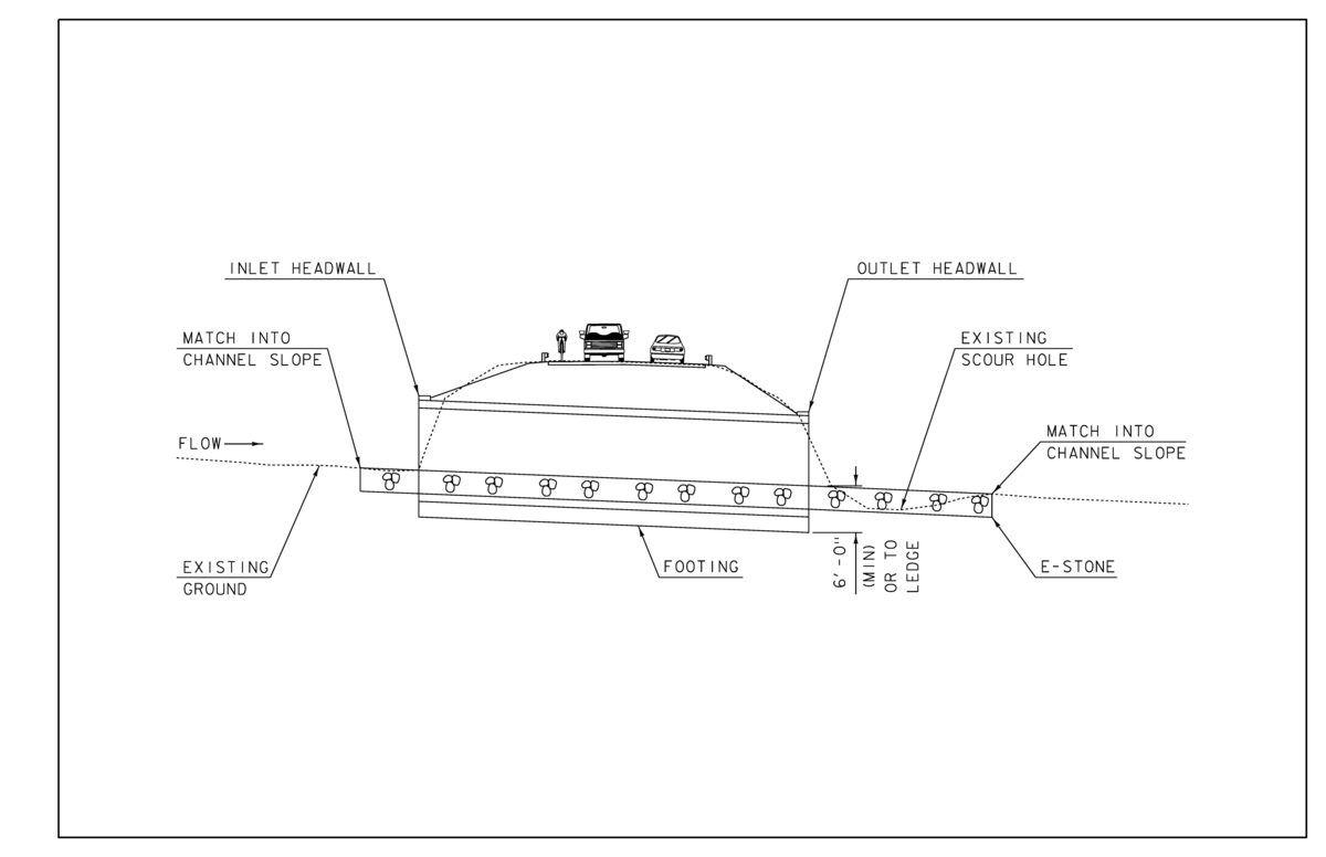
Figure 14: Typical profile of an open bottom arch or frame. Structures should always be constructed on a grade that matches the existing stream slope and be equipped with full height headwalls at the inlet and outlet.
Comparing Open and Closed Bottom Structures
Open and closed bottom structures offer various advantages based on foundation type, however functionally they operate much the same. Closed bottom culverts are embedded below the streambed and infilled with E-stone. Areas with a shallow bedrock profile however, can prove difficult locations to install embedded structures. Solid rock removal can be a costly and time-consuming process. Sites with ledge within the structure footprint may be good candidates for open bottom structures, which commonly employ spread footings. This substructure works to distribute forces along the surface of the footing, which runs the full length of the structure. Spread footings are useful in areas of shallow bedrock as the subfooting may be poured directly to ledge, reducing scour susceptibility, minimizing excavation, and eliminating solid rock removal that would otherwise be necessary to facilitate embedment of a closed bottom structure.
More information: Hydraulics Manual, Section 6.3.1: Structure Type Selection
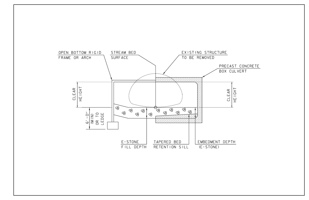
Figure 15: Comparing open and closed bottom structure cross sections. Closed bottom structures do have limitations on span (depending on the fabricator), however at similar spans, these structure types serve the same function. Differences lie in the foundation type and the structure invert. Closed bottom structures have a buried invert and bed retention sills to retain infill material. They should also be equipped with cutoff walls, which prevent undermining of the structure. Open bottom structures provide a natural stream bottom and are commonly founded on spread footings. This type of foundation is conducive to a shallow bedrock profile. To determine if your site may have a shallow bedrock profile, look for exposed ledge within the streambed or take subsurface borings at the project location.
“Equalizer” Box Culvert
This is a unique subset of box culverts that work to equilibrate standing water on either side of the roadway (E.g. a wetland intersected by a road). When this type of structure is recommended, it is anticipated that a buried invert and infill material are not necessary to provide aquatic organism passage and will not be required for the replacement of the structure. ANR River Management should be consulted regarding this determination. The following details are typical for this structure type:
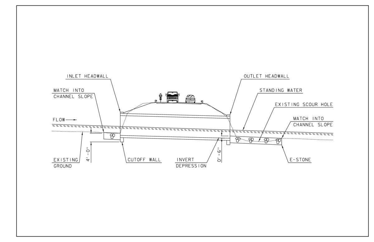
Figure 16: Box culvert profile typical of an “equalizer” structure, which work to equilibrate standing water on either side of a roadway. This structure should be embedded approximately 6 inches, and allowed to silt in over time. As there is no need for infill material, bed retention sills are also not required. Structures should always be constructed on a grade that matches the existing stream slope and be equipped with full height headwalls at the inlet and outlet. A closed bottom structure should also be equipped with cutoff walls, extending to a depth equal to the culvert rise, up to 4 feet, or to ledge, to serve as undermining prevention.
Box Culvert on Intermittent Streams
Intermittent streams are those which do not continuously convey surface water, and generally do not sustain significant populations of aquatic organisms. Structures on intermittent streams are not required to meet state stream equilibrium standards for bankfull width (span length), and do not need to be equipped with aquatic organism passage retrofits such as E-stone and bed retention sills. Infill material however, serves the additional purpose of energy dissipation, reducing velocities and dissipating the erosive force of water. When large velocities are anticipated on an intermittent stream, several retrofits can serve the purpose of energy dissipation. It may be desirable to install a stone fill apron at the outlet to dissipate velocities and prevent a scour hole. Furthermore, roughening the interior surface, which can be achieved through the addition of hydraulic baffles, is another means of achieving energy dissipation. Simplified details are shown in the subsequent figures. If your site is experiencing significant issues with erosion or scour, consult Hydraulic Engineering Circular No. 14 (HEC-14), ANR or the VTrans Hydraulics Unit to determine the appropriate measures to employ at your site.
More Information:
- Hydraulics Manual: Section 6.4.4.2: Outlet Protection
- HEC-14: Hydraulic Design of Energy Dissipators for Culverts and Channels
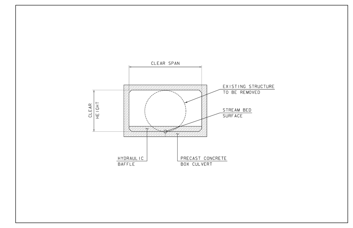
Figure 17: Box culvert section typical of intermittent streams. When specified, this type of structure should be equipped with hydraulic baffles, which are not intended to hold stone, but rather work to reduce velocities, dissipating energy, extent of scour and erosion. The size and shape of baffle can vary based on site constraints, culvert size, and culvert shape. For many intermittent structures, 6-inch baffles, flat across the full width of the structure, are sufficient for energy dissipation. Structures on slopes exceeding 6%, or in locations with a history of damage due to excessive outlet velocities, should be formally designed to minimize risk to the project area.
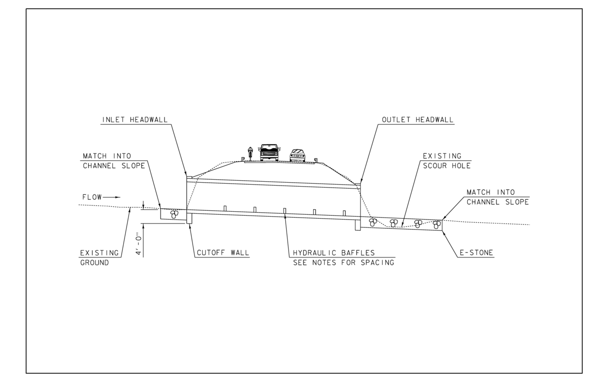
Figure 18: Box culvert profile typical of intermittent streams. High velocities are often anticipated with this type of structure. Stone fill may be required, particularly at the outlet, to reduce erosion and prevent a scour hole. Installation of hydraulic baffles is another measure that may be recommended to increase roughness and dissipate velocities. Approximate hydraulic baffle layout is shown above. There should be no baffle within a distance equal to the culvert opening width from the inlet, to avoid reducing the hydraulic capacity of the structure. The last baffle should be located no closer than L/2 from the structure outlet, where L is the designed distance between baffles. There should never be less than five rows of hydraulic baffles. Structures should always be constructed on a grade that matches the existing stream slope and be equipped with full height headwalls at the inlet and outlet. A closed bottom structure should also be equipped with cutoff walls, extending to a depth equal to the culvert rise, up to 4 feet, or to ledge, to serve as undermining prevention.
Fish Baffles and Liner Projects
Structures under large amounts of fill or in locations where road closures are not feasible, may be good candidates for rehabilitation. To be considered for a liner, the structure must meet state hydraulic and environmental standards for both the existing structure and the proposed lined structure. A lined structure on a perennial stream must comply with environmental standards for aquatic organism passage (AOP). Structures within a mapped flood insurance study region generally preclude liner projects due to floodway regulations on backwater.
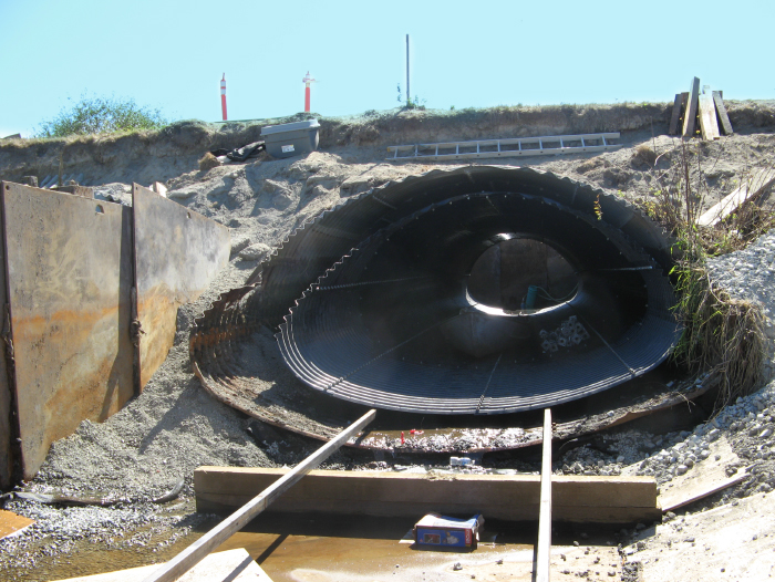
Figure 19: There are various rehabilitation options including a slip liner (pictured), spray-on liner and a paved invert liner. Slip liners are good means of rehabilitation when a smaller but still hydraulically adequate structure can be fit within a host structure. It is important that this structure accommodate AOP. It should be noted that a narrower structure poses the risk of increased velocities and extent of erosion at the outlet. The site must be screened by ANR River Management to determine if the location is conducive to retrofits for AOP and ensure that a narrower structure will meet channel equilibrium standards for bankfull width. ANR Hydraulics should also be consulted to ensure compliance with hydraulic standards.
Fish baffles are commonly used to facilitate fish passage. These retrofits allow for the correction of velocity and flow depth barriers within rehabilitated or lined culverts that would otherwise inhibit fish passage, compromising connectivity with upstream waterways. Baffles are spaced according to the slope of the rehabilitated culvert and the minimum baffle height is based on a target fish species of interest. Structures with significant outlet drops (> 2 feet) or on excessive gradients (> 5%) may not be feasible to retrofit for AOP. ANR River Management needs to be consulted for approval of a liner and can assist regarding the target fish species, baffle spacing and configuration. The following encompasses examples and typical details specified for this type of structure retrofit:
More information:
- The Vermont Culvert Aquatic Organism Passage Screening Tool
- VT SRMPP: Vermont Standard River Management Principles and Practices
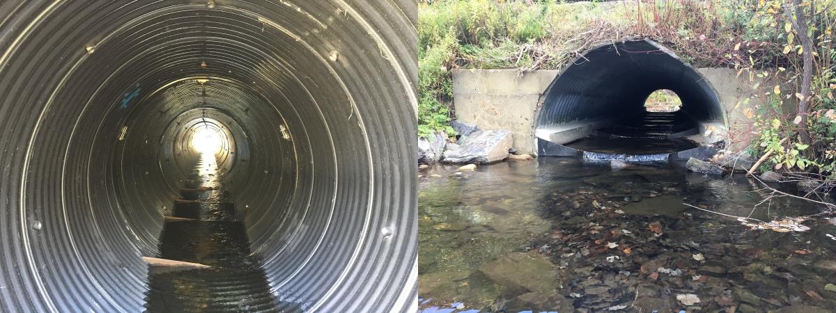
Figure 20: Baffles constructed for fish passage on a corrugated metal pipe (left) and pipe arch (right). Angled baffles are preferred for round pipes and box culverts. These retrofits typically slope from 12 inches on the high side to 6 inches on the low. For pipe arches, 6-inch baffles contoured to the bottom radius are preferred. Baffle spacing should be set according to the culvert gradient. Baffles are typically quarter-inch steel plate with fabricated steel bracing brackets welded to the rehabilitated culvert.
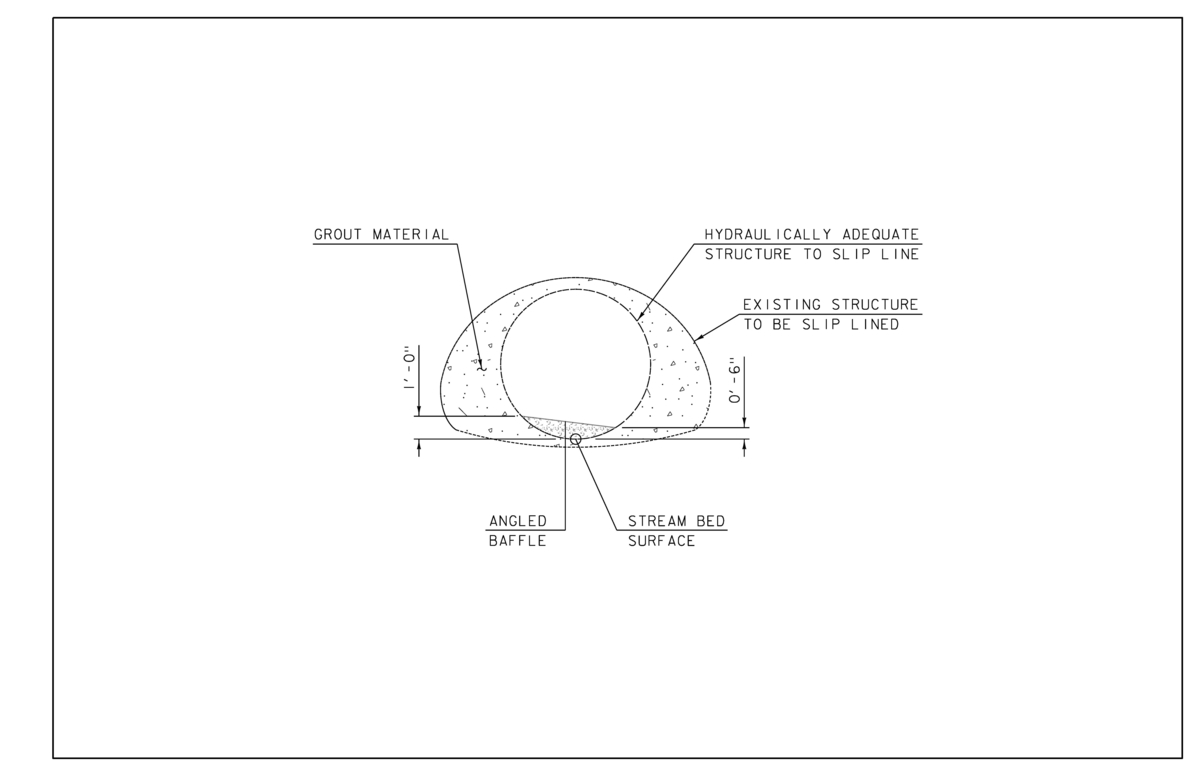
Figure 21: Pipe arch section slip-lined with a circular pipe. Angled baffles are preferred for this structure type, sloping from 12 inches on the high side to 6 inches on the low. Grout is used to fill the space between existing structure and proposed slip line structure. The finished product should be hydraulically adequate, maintain channel equilibrium and provide aquatic organism passage.

Figure 22: Sample profile for a slip-lined culvert and fish baffle configuration based on a 2% grade and target species of Brook Trout. This structure, with a minimum baffle height of 6 inches on the low side, requires 12.5 foot spacing for a drop of 3 inches between baffles. This allows for a depth of water of 3 inches at the next baffle upstream, termed the zero-flow depth. This water depth, specific to the target species of interest, allows Brook Trout sufficient depth to jump the baffle into the next pool. The outlet of the structure should be equipped with a baffle and spaced accordingly to the inlet. The first baffle should be spaced no closer than a distance equal to one culvert rise from the inlet. Rock weirs may need to be installed at the outlet to backwater the outlet baffle. For more information on rock weirs see VT SRMPP page 79. Consult ANR River Management or AOT Hydraulics for design guidance.
Typical Channel Section
The surrounding channel is often disturbed by the construction of a new stream crossing structure. The following typical channel section should be used to recreate the channel at the inlet and outlet, tying into the natural channel configuration at the project limits. This configuration allows the channel width upstream and downstream to be consistent, minimizing velocity fluctuations and extent of erosion. E-stone along the channel base will prevent subsurface flows, providing the conditions necessary for aquatic organism passage. It is permissible for the contractor to use E-stone along the channel banks as well, however VTrans stone should not be used along the channel base, as this is known to result in subsurface flow.
More Information: Hydraulics Manual, Figure 5-1: Typical Stream Channel Cross Section
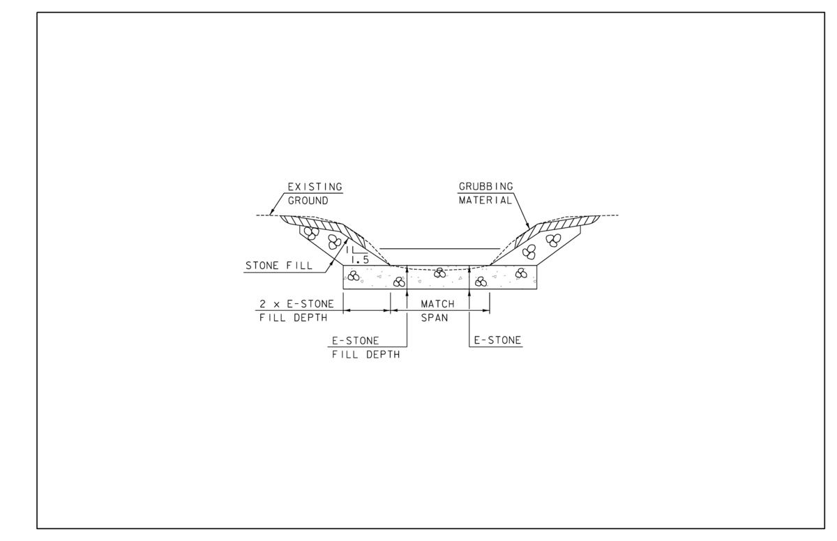
Figure 23: Typical channel section. Disturbed channel sections should be reconstructed in accordance to this figure, in an attempt to emulate the natural channel configuration. Any disturbed channel banks along the roadway slopes, or at the structure inlet and outlet, should be protected with stone fill at a maximum slope of 1:1.5. To preserve channel equilibrium, channel banks should be set apart at a width equal to the structure span. It is recommended that the upper banks be lined with grubbing material or vegetation, as to restore the channel as close as possible to the natural condition.
Previous page: Design Criteria & Standards
Next page: General Comments